This article describes a unique and uncomplicated method of stratified-charging a two-stroke cycle engine which assists in reducing the short-circuited loss of fuel during scavenging. When comparing a two-stroke engine to a four stroke we know that a four-stroke engine is a more efficient power unit. However, due to its inherent simplicity and power to weight ratio, lower manufacturing and maintenance costs and its ability to operate in an inverted environment, the small naturally aspirated, crankcase compression, spark ignition petrol two-stroke cycle engine is most widely used and has met the requirements of many users.
The mysterious drawback with the modern two-stroke cycle engine, however, is its inferior fuel consumption and higher unburned hydrocarbon exhaust emissions when compared with the four-stroke cycle power unit. This arises quite simply to the fact that in a carburetted two-stroke cycle engine be it ‘loop’ or ‘cross scavenging’; the scavenging process is carried out by the mixture of fuel and air. Some of this free charge mixes with the residual exhaust gas as scavenges the cylinder while some of it is lost to ‘short-circuiting’, i.e. fresh charge enters the transfer ports and goes directly out of the exhaust port. The net effect is that some 25% to 40% of air, and inherently fuel are wasted resulting in high fuel consumption and at the same time increasing radically the amount of unburned hydrocarbons in the exhaust in recent years. As the pollution growth has to be controlled, we are concentrating on eliminating the fundamental weakness of the two-stroke cycle engine.
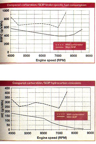
It is quite clear, that should the scavenge process be carried out with air only and the fuel be supplied separately to the cylinder then the air trapping efficiencies wold remain as before (70 & 55%) but the specific fuel consumption figures would be correspondingly improved by 30 & 45% assuming that the combustion and other efficiencies were impaired. The combined effect is that little or none, of the fuel reaches the crank-case and when the scavenge process commences with the opening of the transfer ports, a stratified charging process begins with air only in the proximity of the exhaust port and the rich mixture retained as remotely as possible from the exhaust port. Hence most of the fresh charge lost from the cylinder will be of an air-only composition at best or a very lean air/fuel ratio mixture in the worst case.
After extensive research and market consultations, we concluded that the Simplified Camless Injection Process (SCIP) was a very suitable device which would fulfil our purposes.
The SCIP system is derived from IFP’s compressed air-assisted fuel injection process (IAPAC), in which the fuel is introduced into the cylinder separately from the scavenging air to minimise fuel short-circuiting. The IAPAC system uses crankcase-compressed air to atomise the fuel before it is introduced into the cylinder through a valve opening. But for smaller-displacement engines (up to 200cc), accommodating the cam required to activate the valve necessitated a costly redesign. To avoid this, IFP designed and developed an innovative diaphragm actuation mechanism for small two-stroke engine application.
The main features of the SCIP injector unit are:

The timing and lift of the valve are determined by the pressure signals to the upper and lower diaphragm chambers. The upper chamber is connected to the crankcase. The pressure in this chamber is slightly lower than the crankcase pressure, and its role is to push onto the diaphragm to help the valve opening. The lower chamber is connected to a small port drilled into the cylinder. The opening of this port is controlled by the piston at a timing close to the exhaust opening. The closure of the valve is controlled by the spring retainer. The type of spring (stiffness and pre-stress) is chosen and tuned according to engine displacement, crankcase compression, maximum engine speed, exhaust tuning, etc.
The injector operates at low pressure (about one bar) and is used solely as a fuel-metering device. The atomisation is obtained by the SCIP valve and venturi, and the whole engine revolution cycle (even when the valve is closed) is available for fuel introduction. Hence a fixed injection timing is used. The crankcase position is irrelevant and the low cost electronic control unit only controls the output parameters : fuel pulsewidth and spark timing. In the simplest configuration a mechanical (diaphragm-type) fuel pump can be used to create the low fuel pressure required.
Besides the SCIP injector, the only other additions to the engine are the compressed air circuit, which includes additional reed valves which can be bolted on to the crankcase or included in the inlet reed valve box, and a single pipe which serves as the compressed air tank. The connections between the engine and the SCIP unit will have to be calibrated. In the simpler SCIP configuration with mechanical fuel pump, the system uses less than 10 watts of electricity, and hence no modification of the existing two-stroke power supply for ignition and lights, etc, is required.